Understanding Gear Pump Pressure and Flow Curves
Gear pumps are among the most widely used positive displacement pumps in industrial fluid handling. Their popularity comes from a simple operating principle, reliable performance, compact structure, and stable output under a wide range of conditions. For engineers, buyers, and technicians, one of the most important topics is understanding gear pump pressure and flow curves. These curves explain how a gear pump behaves as system pressure changes, how flow rate is affected by viscosity and speed, and what limitations must be considered during selection and operation.
In practical applications, the relationship between pressure, flow, speed, viscosity, and efficiency determines whether a gear pump will perform well. A pump may deliver strong flow at low pressure, but as resistance increases, internal leakage and mechanical load can reduce output. This is why a clear understanding of gear pump performance curves is essential for industrial process design, hydraulic systems, lubrication systems, fuel transfer, chemical handling, and many other applications.
This guide explains the basics of gear pump pressure and flow curves, how to read performance data, what factors influence output, and how to use curve information for proper pump selection. It also includes a practical table of specifications, a comparison table, and key terminology to support SEO-rich, industry-focused content for general informational use.
What Is a Gear Pump?
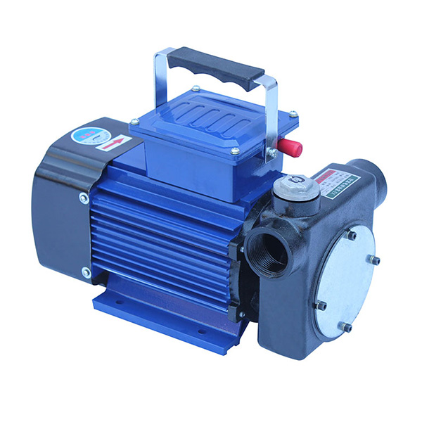
A gear pump is a type of positive displacement pump that moves fluid by trapping it between the teeth of rotating gears and the pump housing. As the gears rotate, fluid enters the suction side, is carried around the outer edges of the gears, and is forced out of the discharge side. Because of this fixed displacement action, gear pumps are known for delivering predictable flow.
The two most common types are external gear pumps and internal gear pumps. External gear pumps use two identical gears that mesh together, while internal gear pumps use an internal and external gear arrangement. Both types are valued for their durability and ability to handle viscous fluids.
Gear pumps are commonly used in:
- Hydraulic power systems
- Lubrication systems
- Oil transfer
- Fuel and diesel handling
- Polymer and resin transfer
- Food and beverage processing for suitable fluids
- Industrial chemical transfer
Why Pressure and Flow Curves Matter
A gear pump pressure and flow curve is a performance chart that shows how flow rate changes under different discharge pressures. In an ideal positive displacement pump, flow would remain constant regardless of pressure. In real systems, however, flow decreases slightly as pressure rises because of internal slip or leakage.
These curves help answer key questions such as:
- How much flow can the pump deliver at a specific pressure?
- How does pump speed affect output?
- What happens when fluid viscosity changes?
- Where does efficiency begin to drop?
- What pressure range is safe for reliable operation?
For system designers, pressure and flow curves are essential because they support accurate pump sizing. For maintenance teams, they help identify whether a pump is operating normally or showing signs of wear, cavitation, or excessive internal leakage. For buyers and OEM engineers, they provide a technical basis for product comparison and specification review.
How Gear Pump Pressure and Flow Curves Work
A gear pump curve typically plots flow rate on the vertical axis and pressure on the horizontal axis. Multiple lines may be shown for different rotational speeds or viscosities. As discharge pressure increases, the delivered flow generally declines slightly. The slope of the curve depends on the design, clearance, fluid properties, and operating speed.
In many charts, the curve is nearly flat at low to moderate pressure, showing that the pump maintains stable output. As pressure approaches the upper operating limit, the curve may slope downward more noticeably due to increased slip, oil heating, and mechanical stress.
Key curve behaviors include:
| Curve Behavior | Meaning | Typical Cause |
| Flat flow line | Stable output across pressure range | Good sealing, proper viscosity, low slip |
| Downward slope | Flow decreases as pressure rises | Internal leakage and efficiency loss |
| Steeper slope at high pressure | Performance drops faster near maximum pressure | Wear, increased clearances, high temperature |
| Different curves at different speeds | Flow changes with pump RPM | Displacement remains fixed, speed changes output |
Basic Gear Pump Performance Definitions
Understanding gear pump performance requires knowledge of several core technical terms. These definitions are useful for reading catalogs, datasheets, and engineering curve charts.
| Term | Definition |
| Displacement | The volume of fluid moved per revolution, usually expressed in cc/rev or in3/rev. |
| Flow rate | The amount of fluid delivered per unit time, commonly in L/min, GPM, or m3/h. |
| Pressure rating | The maximum working pressure the pump is designed to handle safely. |
| Viscosity | A fluid’s resistance to flow, usually measured in cSt or cP. |
| Volumetric efficiency | The ratio of actual flow to theoretical flow, expressed as a percentage. |
| Mechanical efficiency | The ratio of useful output to input after friction losses are considered. |
| Total efficiency | The combined effect of volumetric and mechanical efficiency. |
| Slip | The internal leakage that causes actual flow to be lower than theoretical flow. |
How Pressure Affects Gear Pump Flow
In a gear pump, pressure does not directly create flow; instead, the pump displacement and speed create flow, while pressure determines how much resistance the pump must overcome. As system pressure rises, more fluid tends to leak backward through the internal clearances between gears, side plates, and housing. This leakage is called slip.
Because of slip, the actual flow is always lower than theoretical flow. At low pressure, the difference may be small. At higher pressure, especially when combined with low viscosity or increased wear, the difference becomes more noticeable.
The basic relationship can be summarized as:
- Theoretical flow increases with pump speed and displacement.
- Actual flow decreases slightly as pressure increases.
- Higher viscosity usually reduces slip and improves flow retention.
- Excessive wear increases leakage and lowers efficiency.
This is why gear pumps are often preferred for viscous fluids. Thick fluids leak less internally, allowing the pump to maintain a more stable flow curve under pressure.
Influence of Viscosity on Pressure and Flow Curves
Fluid viscosity has a major impact on gear pump performance curves. Low-viscosity fluids such as light solvents or thin oils tend to leak more easily through internal clearances, which can reduce volumetric efficiency. Higher-viscosity fluids, on the other hand, usually improve sealing between gear teeth and pump housing, resulting in better flow stability.
However, viscosity must be within a practical operating range. If the fluid is too thick, suction conditions may worsen, pressure drop at the inlet may increase, and the pump may require more torque. In cold-start conditions, a highly viscous fluid can create excessive load and potentially damage the drive system.
| Viscosity Range | Typical Performance Effect |
| Very low viscosity | Higher internal leakage, lower volumetric efficiency, flatter pressure tolerance may be reduced |
| Moderate viscosity | Balanced flow, stable operation, common in many industrial fluids |
| High viscosity | Lower slip, improved sealing, but higher torque demand and possible suction limitations |
When analyzing gear pump curves, it is important to confirm the viscosity range used during testing. A performance curve generated with a particular oil grade may not represent the same pump behavior when handling a thinner or thicker fluid.
Gear Pump Speed vs Flow Relationship
Speed is one of the most important variables in gear pump performance. Since a gear pump is a positive displacement device, flow is directly proportional to rotational speed. If the speed doubles, the theoretical flow also doubles, assuming displacement remains constant.
In practice, actual flow follows the same general trend, but pressure and slip will influence the final result. At higher speeds, the pump may deliver more flow, but other limitations such as inlet conditions, fluid heating, noise, and mechanical wear may become more significant.
| Speed Condition | Expected Result |
| Low speed | Lower flow, lower shear, potentially better suction performance |
| Medium speed | Common operating range with balanced efficiency and output |
| High speed | Higher flow but increased heat, noise, and possible cavitation risk |
For optimal results, pump speed should be matched to the required flow rate and the fluid’s suction characteristics. A well-designed curve chart should show multiple speed lines so users can understand how output changes across operating conditions.
Typical Gear Pump Specification Table
The following table provides a general reference for common gear pump specification ranges. Actual values vary by design, size, material, seal type, and application requirements.
| Specification | Typical Range | Notes |
| Displacement | 0.1 to 200 cc/rev | Small units for dosing; large units for industrial transfer |
| Flow rate | 0.5 to 500 L/min | Depends on speed and displacement |
| Working pressure | Up to 250 bar or higher | Depends on pump design and application |
| Speed range | 100 to 3000 RPM | Application-specific and fluid-dependent |
| Viscosity range | 1 to 100,000 cSt | Actual range depends on pump type and fluid behavior |
| Temperature range | -20°C to 200°C | Seal and material selection are critical |
| Efficiency | 70% to 95% | Varies with pressure, viscosity, and wear condition |
Advantages of Gear Pumps
Gear pumps are widely used because they offer a number of operational and economic advantages. These benefits make them a practical choice in many industrial systems where stable flow and robust construction are required.
- Simple design: Fewer moving parts and straightforward construction.
- Compact size: Suitable for space-limited installations.
- Consistent flow: Delivers predictable output in positive displacement applications.
- Good for viscous fluids: Performs well with oils, lubricants, resins, and similar media.
- High pressure capability: Suitable for demanding industrial systems.
- Easy maintenance: Generally easier to service than more complex pump types.
- Wide industrial use: Applicable across many sectors and process conditions.
These advantages make gear pumps a strong choice for applications where reliability and repeatable flow matter more than extreme precision or ultra-low pulsation.
Limitations of Gear Pump Performance Curves
While gear pumps offer many benefits, their pressure and flow curves also show some limitations. Understanding these limits is important for realistic system design.
| Limitation | Impact on Performance |
| Internal leakage | Reduces actual flow as pressure increases |
| Viscosity sensitivity | Performance changes significantly with fluid thickness |
| Pressure and torque load | Higher pressure requires more drive power |
| Temperature rise | Heat can lower viscosity and increase leakage |
| Cavitation risk | Poor inlet conditions can damage components and reduce flow |
| Wear over time | Clearances increase and efficiency declines |
These factors should be considered when reviewing any gear pump pressure curve. A curve is only useful if it reflects real operating conditions, including fluid type, temperature, and speed.
How to Read a Gear Pump Curve Chart
Reading a gear pump curve chart is straightforward once the main variables are understood. Start by identifying the operating speed, then locate the corresponding flow line. Next, find the expected pressure level and read the flow value at that point. Compare this result with the required system flow.
A typical curve chart may include:
- Flow rate vs pressure lines
- Efficiency curves
- Power or torque requirements
- Multiple RPM values
- Different viscosity test conditions
When reviewing the chart, pay attention to the following:
- Whether the pump can meet the required flow at the target pressure.
- Whether the drive motor has enough power and torque.
- Whether the fluid viscosity matches the test conditions.
- Whether inlet conditions support reliable suction.
- Whether the pump is operating near the upper end of its safe range.
Typical Applications Where Curve Analysis Is Important
Pressure and flow curves are especially important in applications where fluid behavior, pressure variation, or load changes affect output. In these industries, accurate curve interpretation can improve system stability and help avoid undersized or oversized pump selection.
| Application | Why Curve Analysis Matters |
| Hydraulic systems | Pressure changes directly affect performance and power demand |
| Lubrication systems | Stable flow is essential for reliable machine protection |
| Fuel transfer | Viscosity and temperature influence delivery consistency |
| Polymer and resin handling | High-viscosity materials require careful pressure-flow matching |
| Industrial chemicals | Compatibility and flow stability are important for process control |
| Oil and grease transfer | Curve data helps determine whether the pump can sustain output under load |
Key Factors That Influence Gear Pump Performance
Several operating factors can change the shape of a gear pump pressure and flow curve. Knowing these variables helps users make better selection and maintenance decisions.
- Fluid viscosity: Impacts internal leakage and suction behavior.
- System pressure: Determines resistance to flow.
- Rotational speed: Directly affects flow output.
- Temperature: Affects viscosity, seal performance, and wear.
- Clearances: Small changes in wear can influence slip significantly.
- Inlet conditions: Poor suction can cause cavitation and reduced performance.
- Material compatibility: Pump materials must suit the fluid being handled.
These factors are interconnected. For example, temperature rise can reduce viscosity, which increases leakage, which lowers flow, which can change the actual performance away from the original curve. This is why real-world system design must consider more than just the pump’s nominal rating.
Internal Leakage and Volumetric Efficiency
Internal leakage is one of the most important reasons why gear pump flow curves are not perfectly flat. As pressure increases, the fluid forces more of the pumped liquid back through microscopic clearances in the pump. This is called slip, and it reduces volumetric efficiency.
Volumetric efficiency can be expressed as:
Volumetric Efficiency = Actual Flow / Theoretical Flow × 100%
In many gear pump applications, efficiency is highest at moderate pressure and suitable viscosity. Excessive wear, low-viscosity fluids, or high temperatures can all reduce volumetric efficiency. A well-maintained pump with proper operating conditions will usually maintain a better curve shape and more stable delivery.
Common Gear Pump Curve Interpretation Mistakes
One common mistake is assuming that a gear pump delivers exactly the same flow at all pressures. In reality, flow is reduced by leakage and operating losses. Another mistake is using a curve created for one fluid type to predict performance with a completely different fluid.
Additional mistakes include:
- Ignoring viscosity differences between test fluid and process fluid
- Overlooking inlet suction limitations
- Assuming maximum pressure is the ideal operating pressure
- Not accounting for temperature rise during continuous operation
- Failing to include wear-related efficiency loss over time
Accurate curve interpretation requires matching the real operating environment as closely as possible. This leads to better pump sizing, fewer performance problems, and more reliable operation.
SEO-Friendly Summary of Gear Pump Pressure and Flow Curves
Gear pump pressure and flow curves are essential tools for understanding how a gear pump performs under real operating conditions. These curves show the relationship between discharge pressure, flow rate, speed, viscosity, and efficiency. Because gear pumps are positive displacement pumps, they provide stable and predictable flow, but actual output is influenced by internal leakage, fluid properties, temperature, and system resistance.
For industrial users, the main advantage of studying gear pump performance curves is improved selection accuracy. Engineers can choose the right displacement, speed, and pressure rating for the application. Maintenance teams can monitor changes in curve behavior as a sign of wear or inefficiency. Buyers can compare products using technical data instead of relying only on general descriptions.
In short, understanding gear pump pressure and flow curves helps ensure reliable fluid transfer, better energy use, longer pump life, and more stable process performance across a wide range of industries.
Frequently Used Keywords in Gear Pump Curve Content
The following keyword phrases are commonly used in technical and SEO content related to gear pump performance, pressure, and flow characteristics:
| Keyword Phrase | Search Intent |
| gear pump pressure and flow curves | Technical understanding and product research |
| gear pump flow rate vs pressure | Performance comparison and curve reading |
| positive displacement gear pump curve | Engineering fundamentals |
| gear pump efficiency curve | Selection and performance analysis |
| gear pump viscosity effect | Fluid property impact |
| gear pump specifications | Product evaluation |
| industrial gear pump performance | Application and system design |
Conclusion
Understanding gear pump pressure and flow curves is essential for anyone involved in pump selection, system design, process reliability, or equipment maintenance. These curves provide a practical view of how a pump behaves under load and reveal the effects of pressure, speed, viscosity, and wear on real-world output.
By reading gear pump curves correctly, users can choose the right pump size, optimize operating conditions, improve efficiency, and reduce failure risk. Whether the application involves hydraulic systems, lubrication, fuel transfer, or industrial fluid handling, gear pump performance data remains one of the most important tools for making informed engineering decisions.
```


 Phone
Phone
Comment
(0)